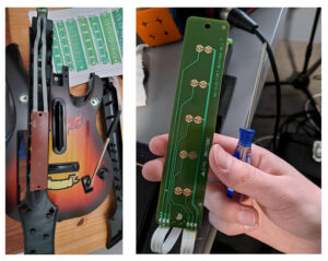
HobbyCNC Frequently Asked Questions

If you have any sales question use the Contact Us page.

All post-purchase support is handled through the FAQ’s (below) and our HobbyCNC Support Forums.

Sales and Ordering

Comparison of HobbyCNC Driver Products

Compare HobbyCNC products – we offer two controller boards, the HobbyCNC PRO and the HobbyCNC EZ.


The HobbyCNC PRO board can be ordered in a 3 or 4 axis variant. Our kits are easy to assemble, compact, reliable and low cost. Only one board to drive 3 or 4 steppers. Many others offer one-board-per-stepper ‘solutions’ which increases wiring complexity and takes up much more space.


Feature Comparison Matrix.

HobbyCNC EZHobbyCNC PRO 3 axisHobbyCNC Pro 4 axis
# of Axis334
Current
(per phase)
3.0 Amps max
600ma (.6A) min
3.0 Amps max
500ma (.5A) min
3.0 Amps max
500ma (.5A) min
Size4.8" x 3.6"
(122 x 91.5mm)
6.75" x 3.5"
(171.5 x 89mm)
6.75" x 3.5"
(171.5 x 89mm)
Steppers Supported5, 6, or 8 wire steppers (4 wire not usable)
Input Voltage24VDC typ
36 VDC max,
12VDC min
36VDC typ
42 VDC max,
12VDC min
36VDC typ
42 VDC max,
12VDC min
4th axis upgradeNoYesN/A
Idle Current
Reduction
NoYesYes
Home/Limit switch
connections
YesYesYes
MicrosteppingYes
1/1, 1/2, 1/4, 1/8, and 1/16

Why choose HobbyCNC

There are a lot of great reasons. Check the “Why choose HobbyCNC page“.

Options to a Parallel port?

Example of parallel port board for controlling HobbyCNC Stepper Motor Driver boards.Yes, there are options to parallel port (not provided by HobbyCNC) that use USB or Ethernet. These jack-up the price considerably, though.

The parallel port allows for the level of direct control required for CNC. There are a couple of options. The easiest and cheapest is usually to find an inexpensive used desktop computer with a parallel port — these can often be found for $60 or less. The second option is to install an EPP compatible parallel port PCI card in your computer. These can be found for under $20 online.

Lastly, there are a couple of companies that offer USB card products with their own plugin to Mach 3 — these offload the realtime requirements from Mach to a DSP chip on the card. The are pricier than either a parallel port or a used PC, but they do offer reliable signals and faster pulse rates than a parallel port can typically offer:


Generic USB-to-Parallel converters will not work.

Generic USB-to-Parallel converters will not work. Although the overall computing demand is low, the timing of the signals on the parallel port is CRITICAL. CAM software depends not only on the signals coming out of the parallel port, but also on the timing of those signals to control the motors. These programs are operating in an effectively “real time” environment to make sure that motions happen at the right speed from multiple axes. Generic USB converters do not maintain the timing associated with the step and direction signals, therefore they are useless for CNC.

Arduino, Raspberry Pi, etc

The HobbyCNC boards are compatible with Arduino, Raspberry Pi and others. HobbyCNC boards accept standard “Step and Direction” TTL level signals via a 25Pin D male connector.

The 25 Pin D connector is a reliable, robust and low-cost connector that is well suited for applications such as this.  The pin-out is designed to be pin-for-pin compatible with a standard PC parallel port, however this does not prevent connecting the board to other systems.

The actual pin-outs of the connectors are provided on each product’s page (scroll to the bottom of the page!)

One way to access these pins is to use a 25 pin D, female, solder connector (Figure 1). You can add only the wires you need.

A steady hand is needed, but this is a good, reliable and inexpensive way to get to the connections.  A “hood” or “shell” is also strongly suggested to protect the wires from the strain of plugging/unplugging (Figure 2).

HobbyCNC 25 pin D Female Solder connector

Figure 1 – 25 Pin D, Female connector, solder cup.

HobbyCNC 25 Pin D Hood

Figure 2 – hood parts (top), assembled (bottom)


Arduino name is a protected trademark of Arduino LLC.
Raspberry Pi is a trademark of the Raspberry Pi Foundation.

Shipping charges outside the United States

See our Terms & Conditions for more details.

If your country is not listed, drop us an email or use the Contact Us page. Countries are added on an ‘as needed’ basis.


Basic Troubleshooting

Have the proper equipment

Having the proper equipment before attempting to assemble the HobbyCNC stepper motor driver printed circuit board (PCB) is strongly recommended.  At a minimum you will need:

  • Example of tools needed to assemble HobbyCNC Stepper Motor Driver kitsSoldering Iron
  • Solder
  • Diagonal Cutters
  • Solder Sucker / Solder Wick
  • Wire strippers
  • Volt meter
  • Small needle-nose pliers
  • Something to hold the board (nice, but not necessary)

HobbyCNC boards are designed with through-hole parts and easy-to-follow instructions to make assembly easy.

The Adafruit site has an excellent article and tutorial that is highly recommended for any newbies.


Do a thorough visual inspection

After each assembly step, before initial power-up and whenever you experience some problem, a thorough visual inspection will often solve 50% of the problems.

Use magnification and good lighting
Make sure you have good lighting and use some type of inspection loupe or, ideally, an inspection microscope (if you are so lucky) and carefully and methodically inspect every connection on the board – paying close attention to any adjacent solder joints (bridging).

Solder Joints
There can be many variations in a solder joint – some are mainly aesthetic (too much/little solder), some are ‘time bombs’ (cold joints) which can work for a while, then at some future date, just ‘crap out’.  Here is an excellent overview of solder joint issues by adafruit.

Solder Bridges
An unintentional ‘blob’ of solder that ‘bridges’ (connects) two pads that are geographically close together.  Most often these can be repaired with a quick touch of a cleaned soldering iron.  Egregious bridges may require a solder sucker or solder wick.

Screw Terminals
It is possible to “torque the hell” out of one of the screws and break the associated solder connection.  Look closely (use magnification)


Stepper Motors

Stepper Motor Wiring and Dimensions

HobbyCNC Stepper Motor Specifications – wiring, wire colors, dimensions, torque curves and instructions on wiring the motors to your HobbyCNC board.

HobbyCNC Stepper Motor Wiring

Pinout and wire colors of my HobbyCNC stepper motors. For other suppliers, you must contact them for wiring and colors.

HobbyCNC Stepper Motor Wiring 23-130-ds8 23-205-ds8 23-305-ds8

Stepper Motor mechanical drawing with dimensions

Stepper Motor Torque Curves

Connecting stepper motors to the HobbyCNC board

Wiring the stepper motors to the HobbyCNC board. Excerpt from DIY CNC Router Plans Rev 03.
HobbyCNC PRO Rev1 board Wiring
HobbyCNC EZ Rev0 board Wiring

Various Stepper Hookups

TYPE# wiresAaCOMCOMbB
HOBBYCNC
8 Wire 130, 205, 305
8REDBLACKYELLOW
BLUE
ORANGE
BROWN
WHITEGREEN
HOBBYCNC
8 Wire 127, 200
8BLUEGREENRED
YELLOW
ORANGE
BLACK
WHITEBROWN
HOBBYCNC6BLACKGREENYELLOWWHITEBLUERED
Vexta PH PK6BLACKGREENYELLOWWHITEBLUERED
Vexta PK8BLACKGREENYELLOW
ORANGE
WHITE
BROWN
BLUERED
Vexta PH8BLACKORANGEBLK/WHTRED/WHTYELLOWRED
8 WireORG/WHTYEL/WHT
Japan Servo,
SKC, Superior
6WHT/REDREDBLACKWHITEWHT/GRNGREEN
Superior8WHT/REDREDWHITE
BLACK
WHT/BLK
ORANGE
WHT/GRNGREEN
SKC6BROWNORANGEBLACKWHITEREDYELLOW
SKC6BLACKGREENBLK/WHT
GRN/WHT
RED/WHT
BLU/WHT
BLUERED

Stepper Motor Current Calculator

Idle Current Reduction must be disabled PRO board only – install J4 on all the 8-pin headers when setting the voltage.

Re-visit the Vref voltages at the test points where the max current is set for the stepper motors. Compare with the assembly instructions.

You can adjust this setting while the motors are running. If this setting is too low (or zero) the motors will not move reliably or may not move at all.

Use the calculator to the right to determine the voltage that must be present at the small test pad next to the blue trim pot.

Microstepping Configuration

[stextbox id=”alert” defcaption=”true”]Don’t use microstepping to increase the “precision” of your machine.[/stextbox]


The HobbyCNC driver boards allow five different modes of driving your stepper motors.  These can be set differently between each axis if desired.  As a side note, 1/8 and 1/16 stepping MAY require quite a lot of computer process power!

We recommend using 1/2 or 1/4 step.  This produces almost full power and usually avoids any resonance issues. The finer the micro step the less power you’ll have.

The Microstepping is set as follows. Note: The right-most jumper is for Idle Current Reduction and is on the PRO boards only.


J1J2J3
1/1 StepONONOFF
1/2 StepONOFFOFF
1/4 StepOFFONON
1/8 StepOFFONOFF
1/16 StepOFFOFFON


You will need to set your CAM software to account for the microstepping. I have my HobbyCNC board set to 1/2 microsteps but forgot to set this in my CAM software and I came out with little-bitty parts (1/2 size).

In Mach3 it appears you need to multiply steps per revolution of the motor times the microstep setting to derive “Pulses Per Revolution”. (I think)

LinuxCNC Microstepping Configuration Screen

LinuxCNC Microstepping Configuration. Repeat for each axis. This is set in the StepConfig wizard.

Stepper motors are running hot

Stepper motors do tend to run hot. They are kept under power regardless if they are moving or still. They can easily reach 80°C (176°F) or higher.

For example, one of our 305 oz in motors is rated at 3 amps into 1.4 ohms per coil. Power = I2R, or 32 * 1.4 = 12.6 Watts per coil, 4 coils = 50.4 Watts. That’s a LOT of heat to get rid of.

Any heatsink you can mount the motor to will help. Try a 6 x 6 inch square of aluminum. mount this so it is between the motor and the mill, in intimate contact with the motor. This should help quite a bit. Naturally, the larger the heat sink surface area, the better. Some users add a small fan like for a CPU chip on a PC. Any airflow will help.

I run my steppers without heatsinks and they run too hot to touch for more than a few seconds.

I did a quick-and-dirty test on my test setup, with a fan, the heatsink on the driver chips sat at 115°F (46.1°C). The motors (no heat sink) were 112°F (44.4°C). The system will run all-day-long at these temperatures. Naturally, the lower you can get them, the better!

Missing steps – motor not behaving properly

If one axis is ‘misbehaving’ (not spinning, missing steps), then you need to isolate the issue. The problem could be:


[stextbox id=”alert”]IMPORTANT

Before touching ANY of the stepper motor wiring – ensure there is 0.0 volts at TB6 (PRO) or TB5 (EZ). Connecting/disconnecting steppers with voltage on the board is an excellent way to blow a driver chip.

[/stextbox]


Did you just move/change your system?

For whatever reason, moving or changing your system is a common cause for things to “just stop working”. Triple-check all wiring, especially the stepper motor wiring. Check all connectors, connections and the screw terminals connecting the steppers to the board.

Excessive torque on the small blue connectors on the PC board can crack the solder joint, so if all else fails, check the underside of the board at the connector joints.

Bad stepper / bad wiring

Disconnect the power.

Do a very careful visual inspection of PC board starting at the screw terminals and working ‘inward’. Double-check the wiring from the PC board to the stepper.

  • Colors are going to the right wires?
  • Connections all solid?
  • All wires inserted in the screw terminals are properly stripped ?
  • Especially check the solder connections at the screw terminals. Over-torquing can break the solder joints.

At the terminal blocks on the PC board, swap the ‘bad’ motor and wiring with a known ‘good’ motor and wiring. Double-check the wires/colors/order before power-up.

The problem stays with the axis. Now the ‘good’ motor is not working and the ‘bad’ motor is. This eliminates the stepper and wiring from consideration. Jump to Solder / assembly problem.

The problem moves with the motor. If the ‘bad’ motor is still bad, then the problem is in the wiring or the motor.

Swap a ‘good’ motor with a ‘bad’ motor at the motor-end of the cable. If the problem ‘moves’ with the motor – bad stepper. If the problem stays with the same axis – wiring problem.

Overheating Stepper

The steppers will run warm-to-almost-hot. They are turning a lot of current into motion. However they should NOT be hot enough to burn you. If the stepper is running very hot, consider some type of heatsink to dissipate that extra heat.

Slipping Coupler

Make sure your coupler between the motor and the drive screw/belt is not loose and slipping. This can create what looks like “missed steps”.

Wiring Problem

It is easy to ‘mix up’ the wiring from the steppers to the board. Most likely, the wiring used between the motor and the board has different colors than the motor. To minimize problems:

  • Never use wire nuts. They might be OK for a bench test, but NEVER in actual use. Wire nuts are designed to remain motionless for their entire lives, not to be whipping around on a dirty, vibrating mill.
  • Wire all 3 (or 4) motors identically.
  • Inspect each connection carefully – wires that are not carefully stripped can break, wires can be improperly stripped when put into the screw terminal
  • Firmly but gently pull on each wire individually going into the screw terminal to confirm each is properly clamped in the terminal strip.

Solder/assembly problem

See FAQ: Do a thorough visual inspection

Power Supply

Check your Power Supply voltage. Do you have sufficient voltage to drive the necessary current to the stepper motor. Low voltages (like 12V) will not provide ideal performance. I’d suggest around 32-36 Volts DC and 7-10 amps (3 motors = 7 amps, 4 motors = 10 amps).

Is your power supply SPECIFICALLY DESIGNED to supply and receive very large current spikes that are typical of driving stepper motors? Just because the power supply is advertised as “36 Volts DC at 10 Amps” does not indicate it’s ability to drive large inductive loads.

PRO: It should be between 12 and 42 Volts DC when the motors are all running. Under no circumstances should the supply exceed 42 VDC.

EZ: It should be between 12 and 36 Volts DC when the motors are all running. Under no circumstances should the supply exceed 36 VDC.

Microstepping

Check microstepping jumpers. If you have no microstepping jumpers installed (J1, J2, J3) on the 8 pin headers (PRO) or 6 pin headers (EZ), then the motor for that axis will not move. You must install the jumpers to enable your desired microstepping. See FAQ Microstepping Configuration.

Disable microstepping (set to 1:1). I suggest you keep it disabled during initial testing and start-up.

Read the FAQ Microstepping. Ensure your software is set to match.

We recommend using 1/2 or 1/4 step. This produces almost full power and usually avoids any resonance issues. The finer the micro step the less power you’ll have.

[stextbox id=”warning”]

Do not use microstepping to increase the “precision” of your machine.

[/stextbox]


Motor current settings

Idle Current Reduction must be disabled PRO board only – install J4 on all the 8-pin headers when setting the voltage.

Re-visit the Vref voltages at the test points where the max current is set for the stepper motors. Compare with the assembly instructions.

You can adjust this setting while the motors are running. If this setting is too low (or zero) the motors will not move reliably or may not move at all.

Use the calculator to the right to determine the voltage that must be present at the small test pad next to the blue trim pot.


Idle Current Reduction

Disable the idle current reduction by installing J4 in all of the small, 8-pin headers (PRO board only). Idle current reduction can cause missed steps in some applications.

Bad driver chip / overheating driver chip

[stextbox id=”info” caption=”The ‘lock-up test'”]With the power applied to the HobbyCNC board, does the stepper motor “lock up”? That is, can you NOT turn it easily by hand? If the motor is ‘locked-up’, then the driver chip is most likely fine.[/stextbox]

Did it smoke? Does it get hot? If you can’t hold your finger in it for more than a second-or-two, then it’s running too hot. Add a heatsink and fan or back-off on the current. The driver chips have a thermal shutdown feature to protect themselves.

Do a visual inspection of the parts around the chip. CAREFULLY inspect all the solder joints on the driver chip. Are all parts installed in the right orientation? No parts burned. No discoloration of the PCB under any part?

More than likely a loose connection did the chip in or a poor (cold) solder joint. Check the terminal block for continuity at each pin. Over tightening the wire screws CAN fracture the corresponding pin.

Did you futz with any of the stepper wiring while the board was powered?

Bad/wrong parallel cable

Not all 25 pin M-F cables will work. It needs to have all 25 pins wired, 1-to-1, or “straight through”. A 25 pin M-F serial cable will not work (see blog post Blown Chip #2), even if it says “straight through” on the data sheet – most serial cables do not have all the pins connected. You can confirm this with steady hands, a volt meter and a paper clip.

Axis binding

Is there something causing binding on that particular axis? Try turning the axis by hand (no power to the motor) through the entire movement range and confirm that everything moves smoothly.

Software sending steps too fast

Slow down the acceleration and velocity A LOT for that axis (like 0.5 IPS / 30 IPM). If it starts working, then slowly increase them until the problem appears. Back off.

Also check if your software can ‘invert’ the step signal. Our boards want “Active High”.

Different movement one direction of rotation vs. the other direction

Check for proper orientation of the RN resistor networks.


Advanced Troubleshooting

Assembly Tips & Tricks

R.T.F.M.

It is highly encouraged to follow the provided instructions. The build instructions are methodical on purpose – build a bit, then test.  Build a bit more, then test.  Trust me, this will make your build more enjoyable (and more likely to work the first time).

Preventing shorts during testing/use

Strongly recommend to put some ½”-1” hex standoffs at all 4 corners of the board to keep the copper side off any possible place to short out while testing, at the very minimum place it on a clean cardboard or folded shopping bag.

First test under power

We suggest NOT using your 36V 10 Amp power supply until you have done the initial testing. Why you ask? Well, if you have a hard short, 10 Amps is likely to turn one of the traces on the board into vapor.

We suggest a 12 VDC “wall wart” 500ma or so as a safer alternative, always test the output of any power supply for correct voltage and polarity before making any connections. You can put a piece of tape or tie a knot in the + lead so you know which is which.

Connect power to TB6 observing +/-, if you’re using a 12V wart, the 24 V fan terminals will not show 24V. Check the 5V test point to negative side of TB6, got five volts good, if not unplug the power supply and examine the board again.

Testing Voltages

All power to the board comes through U7 the LM317HVT regulator, make sure it’s in the right way and that R14 and R15 are the correct values, you can test U7 by measuring from TB6 (-) to the tab of U7, it should be about the same as across TB6 or 30-31 VDC if you are supplying 36V at TB6.

If the voltage at U7 is good, test to the tab of U5, this is the LM317 that supplies the 5 volts, again check it’s in the right way, and that R13 and R16 are the correct values.

The “Before you ask for help” Checklist

  1. Do you have the proper voltage supplied to the board?  (TB5 for EZ, TB6 for PRO)
    And the correct polarity?
  2. Is your Power Supply capable of delivering sufficient current?
  3. Is the test point at 5V?
  4. Have you set the V-ref?
  5. Do you have microstepping jumpers installed? No jumpers – no motor lock/movement.
  6. Are the motors wired correctly?
  7. Do the motors lock up, in other words can you turn them by hand with power applied?
  8. Is your cable a straight through 25 pin, with ALL 25 pins wired?
  9. Have you checked that your software settings are calling the right step & direction pins and port?
  10. Have you checked your system to see what address your port is?
  11. What computer and OS are you running?
  12. Have you tried another software program to see if the problem is the same?
  13. Have your stated the problem/error clearly so that people can understand it?

Asking for help

Use the HobbyCNC Forums.  We are fortunate to have an engaged and intelligent user base that is always willing to offer help.

Consider to cut-and-paste this and answer the questions – this will help the people you want to help you!

  1. Computer: ___________
    Operating System: _____________
    CAM Software: __________
    CAM Software version: ____________
  2. I verified
    1. Power (and polarity) to the board.
    2. Test point at 5V.
    3. Power supply able to deliver enough current.
  3. V-ref is set to ____________ VDC.
  4. I have [3|4] _____________ oz-in steppers.
  5. I have double-checked the stepper motor wiring.
  6. I have microstepping enabled
  7. The motors [do | do not] lock up (can turn them by hand with power applied).
  8. I have confirmed I have a straight through 25 pin with ALL 25 pins wired.
  9. I have checked that my software settings are calling the right step & direction pins and port.
  10. I have checked my system to confirm the address for the parallel port.
  11. I [have | have not] tried another software program to see if the problem is the same.
  12. Description of the problem:


Special thanks to Kristin for these tips.


Board Assembly Instructions

Downloadable assembly instructions for all HobbyCNC boards and kits. PDF format.

HobbyCNC PRO 4-Axis Rev 2

4 axis PRO Assembly Instructions (PDF)
PRO board mounting template (PDF). Print at 100%


HobbyCNC PRO 3-Axis Rev 2

3 axis PRO Assembly Instructions
PRO board mounting template (PDF). Print at 100%


HobbyCNC PRO Rev 1

This board has been replaced by the Rev2. 3 and 4 axis PRO instructions


HobbyCNC EZ

3 axis EZ Instructions (PDF)
EZ board mounting template (PDF). Print at 100%

If you are more visual, see the detailed instructions, with step-by-step photos on Instructables.com


HobbyCNC PRO 4th Axis Upgrade

4th axis Upgrade Kit Instructions

Heat Sinks

Per the instructions: “We recommend fan (24VDC) cooling and heatsink at 2A or more.  The wiring diagram has a suggested heatsink from 1/8” aluminum flat stock.

We suggest you insert the driver IC’s into the PC board, and screw the driver ICs to the heatsink before soldering. This will eliminate any stresses on the driver IC leads and package. The heatsink is marked where to drill the holes if you install the heatsink before soldering. If you install the heatsink after you have soldered-in the driver ICs, you will need to mark your own holes.

Heatsink compound (thermal paste) is also strongly recommended before attaching the heatsinks.

HobbyCNC EZ Heatsink

The HobbyCNC EZ ships with a 2″ x 4.5″ x 1/8″ aluminum heatsink (Fig 1) and (6) 4-40 machine screws. The heatsink is marked for drilling and tapping (Figure 1, red arrows, drill & tap 4-40) if you install the heatsink before soldering the driver ICs. If you’ve got the drivers already soldered-in then you will need to mark and drill holes to match where the IC’s ended-up.


HobbyCNC EZ heatsink HobbyCNC for DIY CNC, DIY CNC router, DIY CNC Mill, DIY robot control. Low cost high performance stepper driver.

Figure 1 – Drill and Tap (6) places – Use these marks ONLY if installing the heatsink BEFORE soldering in the driver ICs.

HobbyCNC PRO Heatsink

Optional HobbyCNC PRO, 2″ x 6.25″ x 1/8″ aluminum heatsink (Fig 2) and (8) 4-40 machine screws. It is marked for drilling and tapping (Figure 2, red arrows, drill & tap 4-40) if you install the heatsink before soldering the driver ICs.Watch the  video on installing the driver chips and heatsink. If you’ve got the drivers already soldered-in then you will need to mark and drill holes to match where the IC’s ended-up.

HobbyCNC PRO heatsink. HobbyCNC for DIY CNC, DIY CNC router, DIY CNC Mill, DIY robot control. Low cost high performance stepper driver.

Figure 2 – Drill and Tap (8) places – Use these marks ONLY if installing the heatsink BEFORE soldering in the driver ICs.

If you want to make your own heatsink, here is a drawing with the hole center dimensions. Make the heatsink first (if possible) and attach the driver IC’s before soldering. HobbyCNC PRO_Heatsink drawing.

Unused Axis

You can leave an unused axis disconnected (no motor).  Turn down the Vref if you like also.

CAUTION: Ensure there is NO POWER to the HobbyCNC board when connecting or disconnecting motors.


Parallel Port Pinouts

Pin #Description
1*Enable (option)*
2X Direction
3X Step
4Y Direction
5Y Step
6Z Direction
7Z Step
8A Direction
9A Step
Pin #Description
10Limit**
11A Home**
12X Home**
13Y Home**
15Z Home**
1*, 14, 16, 17***
18-25Ground

*     Power Reduction can be enabled (Active High). Refer to the HobbyCNC PRO manual for details.
**   Pins 10, 11, 12, 13 and 15 are pulled up with a 10K resistor and are used for home/limit functions.  Consult your software as to the type of switches needed. (N.O. or N.C. types). The actual function of these pins is determined in your CAM software.
*** Pins 1, 14, 16 and 17 are not pulled up and are available as needed. Our driver board plays no role other than to provide convenient access to these pins. Pins are made available via solder pads (P6). Nothing is done to these lines on the PRO board.


HobbyCNC EZ Parallel Port Pinouts

Pin #Description Pin #Description
2X Step 10Limit*
3X Direction 11Z Home*
4Y Step 12X Home*
5Y Direction13Y Home*
6Z Step18-25Ground
7Z DirectionAll othersNot Connected

Pins 10, 11, 12, 13 and 15 are pulled up with a 10K resistor (RN4) and are used for home/limit functions.  Consult your software as to the type of switches needed. (N.O. or N.C. types)  Limit switches are usually wired in a series as N.C. and the home switches are wired individually for that axis.

Checking Voltages

Start at the beginning

Check the supply voltage at TB5 (EZ) or TB6 (PRO).

BoardMin
Voltage
Typical
Voltage
Max
Voltage
Suggested
Current
PRO (3 or 4 axis)12VDC36VDC42VDC10A (4 axis)
7.5A (3 axis)
EZ12VDC24VDC36VDC7.5A

See the Power Supplies FAQ for more info on delivering power to the boards.

Check 24V at the fan connector

Confirm 24 Volts at the fan connector at TB6 (EZ) or TB7 (PRO). This voltage will be affected by your power supply voltage. If your power supply is less than about 26 Volts DC, then you will read less than 24 Volts at the fan connector (roughly 2 volts less than your supply voltage)

Do you have anything besides a fan connected to this connector? the MAXIMUM draw from this connector is 300mA (0.3A) without a heatsink. Connecting anything other than a fan is not advised.

Confirm 5VDC at test point

Check The test point labeled +5 VDC.  Put the negative (black) meter lead on the “-” (minus) of the power connector TB5 (EZ) or TB6 (PRO).  Put the positive (red) meter lead on the +5 VDC test point

99% of the time this is a solder bridge somewhere on the board. Examine the board under bright light with a magnifying glass, I found my short on the component side between the two rows of pins of one of the driver chips, very hard to see.

Do you have anything else drawing from the 5 Volts on this board (like a relay board or an opto board)? Don’t do that. The regulators on this board are designed to support this board ONLY, and a fan (see “Check 24V above)

Voltage at the Axis test points

Each axis has a blue-topped variable resistor (trim pot) to set the amount of current provided to each stepper motor. Measure the voltage at each TP (located physically next to that blue-topped variable resistor). Put the negative (black) meter lead on the “-” (minus) of the power connector. Confirm against the manual.

Use the calculator to the right to determine the proper voltage for the desired current. This is for both the PRO and EZ boards.

Regulator getting hot

This would likely indicate excess current draw somewhere ‘down the line’ from the regulator.

Which regulator is which

PRO – 24V = U6.   5V = U5.    “Pre regulator” (enables higher input voltages on PRO board) = U7

EZ – 24V = U5.   5V = U4

No motor movement

Check your Step and Direction settings

If your motor is “locked” with power applied but they just “twitch” rather than step, then it’s most likely you’ve got your Step and Direction signals backwards coming into the board.
Check your software and compare to the setting in the manual or on the PRO or EZ pages. Reversing Step and Direction will result in the motor twitching randomly as it tries to step on the far less frequent direction signal change.

Check microstepping jumpers

If you have no microstepping jumpers installed (J1, J2, J3) on the 8 pin headers (PRO) or 6 pin headers (EZ), then the motor for that axis will not move – you will be able to turn the motor by hand even with power connected.. You must install the jumpers to enable your desired microstepping. See FAQ Microstepping Configuration.

Verify stepper wiring

It’s easy to get the wiring from the stepper to the board messed-up.  If the steppers whine or twitch, but do not spin, you likely have a wiring mix-up.

Make double-sure you know the wire colors and polarity of your coils, and you’ve got them hooked-up to the right spots on the board. Check the Stepper Motor Wiring FAQ for HobbyCNC stepper motors, as well as a few others.

Did you just move/change your system?

For whatever reason, moving or changing your system is a common cause for things to “just stop working”. Triple-check all wiring, especially the stepper motor wiring.

Check Power

Confirm power switch is on.

Verify fuses not blown.

Visual inspection of all Power Supply wiring – no shorts, no broken wires, no loose connections at terminal blocks, no bad/broken solder connections, any crimped connectors are sound and secure.

Measure voltage at input to board:

BoardMin
Voltage
Typical
Voltage
Max
Voltage
Suggested
Current
PRO (3 or 4 axis)12VDC36VDC42VDC10A (4 axis)
7.5A (3 axis)
EZ12VDC24VDC36VDC7.5A

IF the steppers lockup when power is applied (even without computer connected) then issue is with computer/parallel port/ cable.  Thousands of boards and minimal (like none) issues with motherboard/parallel port.

Microstepping Configuration

[stextbox id=”alert” defcaption=”true”]Don’t use microstepping to increase the “precision” of your machine.[/stextbox]


The HobbyCNC driver boards allow five different modes of driving your stepper motors.  These can be set differently between each axis if desired.  As a side note, 1/8 and 1/16 stepping MAY require quite a lot of computer process power!

We recommend using 1/2 or 1/4 step.  This produces almost full power and usually avoids any resonance issues. The finer the micro step the less power you’ll have.

The Microstepping is set as follows. Note: The right-most jumper is for Idle Current Reduction and is on the PRO boards only.


J1J2J3
1/1 StepONONOFF
1/2 StepONOFFOFF
1/4 StepOFFONON
1/8 StepOFFONOFF
1/16 StepOFFOFFON


You will need to set your CAM software to account for the microstepping. I have my HobbyCNC board set to 1/2 microsteps but forgot to set this in my CAM software and I came out with little-bitty parts (1/2 size).

In Mach3 it appears you need to multiply steps per revolution of the motor times the microstep setting to derive “Pulses Per Revolution”. (I think)

LinuxCNC Microstepping Configuration Screen

LinuxCNC Microstepping Configuration. Repeat for each axis. This is set in the StepConfig wizard.

Power Supplies

Sizing the power supply voltage and current is important to ensure your system performs at it’s best.

Voltage & Current

The stepper power supply MUST be capable of providing 50% of the TOTAL current draw of the steppers.  A 2.5A stepper will draw 5 Amps!  For example:  4 steppers rated at 2.5A will draw a total of 20Amps.  Adequate fusing must be used on both the AC and DC side.

BoardMin
Voltage
Typical
Voltage
Max
Voltage
Suggested
Current
PRO (3 or 4 axis)12VDC36VDC42VDC10A (4 axis)
7.5A (3 axis)
EZ12VDC24VDC36VDC7.5A

Regulated or unregulated

Unregulated linear supply is fine.  A regulated supply or a switching supply will also work well, but you’re paying a lot more for regulation you don’t need.

Typical Unregulated Power Supply Design

The circuit shown below should be adequate for most applications. It is the classic unregulated linear power supply.

CAUTION A few words of caution are in order. First of them concerns working with 115/220VAC. NEVER work on the circuit with the plug in the outlet! BE very careful. It is lethal!!

A well ventilated metal or plastic enclosure is highly recommended. Secondly, be very careful not to short the terminals of the capacitor. A painful shock will result. I suggest several layers of black tape over the screw terminals before applying any power to it. The Bridge Rectifier will get warm, mount it accordingly. Lastly, builder and/or user of this circuit assume all risks and liability with it. It is presented here as a reference only.

Values given are adequate for the loads. Feel free to “upscale” them if you wish. For example, the 35,000uF capacitor, its OK to use higher values for sure in both capacitance and working voltage. I would NOT downsize the Bridge Rectifier.
The Bleed Resistor is required. Ok to use 2 4K 1/2W in parallel, or 3pcs 5.6K 1/2W in parallel.

HobbyCNC Power Supply Example

Switching Power Supplies

I’m of mixed feelings about using switch mode power supplies (SMPS). I won’t use one for my motor drivers. Many SMPS are not designed to handle large inductive loads like stepper motors. However, I don’t seem to hear a lot of complaints about them failing either. There seems to be lots of cheap switchers available on eBay and other places (see my warning on The lowest price DIY CNC electronics isn’t always the best value). As my daredevil friend from Hawaii says “What could possibly go wrong?”.


SMPS are designed only to “deliver” power out to a passive load.
No ability for absorbing regenerating power from the Drive-Motor (Servo). When regenerating, the SMPS might be damaged!
SMPS are very sensitive to Inductive loads that “typically” create spikes, transients, surge voltage. In extreme cases the SMPS might be damaged!
The voltage regulation might be a disadvantage when regenerating. In regeneration/ braking, the load transfers power back to the power supply “enforcing” voltage increase on the terminals of the SMPS. When the terminal voltage exceeds the “set Voltage” of the SMPS, the close loop might  fall “out of loop.” The recovery might last too long and at this point there is no output voltage from the SMPS. “No Power, No Servo!”

No peak current/ power capability.
The SMPS is designed to deliver continuously the rated power. It can’t deliver peak currents that are crucial for Servo operation.

Source, www.elmomc.com


Beware the cheap eBay Chinese switch mode power supplies

It might work. It might not. It might be safe, it might not. You are on your own here, proceed at your own risk.

What’s the difference? 36 VDC is 36 VDC, right? Not right. If your knock-off supply can’t deliver huge bursts of current as demanded to move stepper motors, or it can’t handle the back EMF from a stepper, then you might find slow speeds and low torque. Caveat Emptor.

Here’s a comparison between an ultra-cheap and a quality power supply by loneoceans published on Jan 18, 2015. All I’m saying is look at the difference in components and construction. Then again, you can by 2 of the cheapies for 20% the cost of a quality unit. Pick your poison.

Home & Limit Switches

HobbyCNC PRO Home & Limit Switches Connection

HobbyCNC PRO Home & Limit Switch Hookup (PDF)


Limit Switch Wiring

HobbyCNC - Home & Limit Switches for DIY CNC or CNC Router systemLimit switches are located at the ends of mechanical travel for each axis. The idea is to shut-down the system should it try to go past its stops. Typically, there are two limit switches per axis, and all are wired in series – such that if any one switch is ‘tripped’ (e.g. “opened”), it will break the circuit and shut down the motors.

All limit switches can be wired to use just one input pin on the HobbyCNC board. You CAN use pin 11, 12, or 13. Most software allows you to pick the pin in the setup.


Routing home & limit switch wiring

Of considerable concern is how to run the wiring for the limit switches. Ideally, you want to keep them far away from “noisy” wires that are connected to the stepper motors. There is a potential for these power wires to ‘induce’ an unwanted current in your limit switch circuit which has the potential to simulate a “limit” situation. This is not a happy time.


How does a snap-action microswitch work?

Very nice YouTube video by Cecil Colvin


Q: I have a Hobby pro cnc board. I want to use magnetic proximity switches for the limit switches. They come as PNP or NPN. What on will I need for my board?
A: Our board simply provides a convenient method to connect to the DB25 connector. Our board plays NO OTHER part. Period.


Excellent discussion of home and limit switches

In section 4.5 of the Install and configuration guide for Mach3 which can be found on the MACH3 Product Manuals Page.


Spindle (relay) control

HobbyCNC PRO Output Pins, CNC Spindle Ccontrol, CNC Rrelay control

Figure 1 – HobbyCNC PRO Output Pins

To add spindle control, the HobbyCNC PRO board (Not the EZ) provides easy solder-pad access to four generic ‘output’ pins – Pins 1, 14, 16 & 17 (Figure 1). These pins are typically configured in your CAM software to control different functions – e.g. a spindle or a coolant pump.

These 4 pads are ‘courtesy’ pins that connect directly to the D connector. There is nothing else connected to these pins (as indicated by “NO PULLUPS”). So, technically, we (HobbyCNC) don’t support any type of control – we only pass these wires through from the 25pin D connector for these 4 signals. If your control software sends the proper signals through these pins, then you are in great shape.

Connecting to a spindle or pump

For simple on/off control of a pump or spindle, some type of relay (or equivalent) is required to allow the low voltage/low current of the computer to drive a high voltage/high current output. A spindle can easily draw 10 amps at 120 Volts AC. Some examples of how to do this are provided here:

Relay-drivers-update-rkb.pdf

Does your board support VFD or PWM?

Do you support VFD (Variable Frequency Drive), PWM (Pulse Width Modulation) or PDM (pulse density modulation)?

As stated above, the HobbyCNC board does not ‘support’ any type of output control (except the stepper motors). On the HobbyCNC PRO board, four pins are provided that will output whatever signal(s) are generated by your software.

Some videos suggested by our users

LinuxCNC Huanyang VFD, home switch, and joypad configuration

Homemade DIY CNC, How to control a Huanyang VFD inverter with Linux CNC


Arduino/GRBL Shield Kit

Can I use the same 5V supply that I use for the Arduino?

There are two answers to this question:

Yes. Using the same 5V supply as the Arduino will work. HOWEVER, you will NOT HAVE ELECTRICAL ISOLATION – which is THE reason I included the opto isolators.
You might need to replace D1 with a plain piece of wire, as I count on it to take 0.7V out. but I’m guessing this won’t be an issue.

No. I included a separate, isolated, power supply on purpose. This is necessary if you want true electrical isolation between the ‘real world’ and your Arduino board (Strongly Recommended!)

So, there you have it. You pays your money, and you takes your chances.

BrianV

Is the Arduino/GRBL shield available assembled?

Sorry, it is not.

Does the Arduino/GRBL shield require a HobbyCNC driver board.

Not really. It is designed to work the cleanest with the HobbyCNC Pro boards.
However, it does output the traditional “Step and Direction” signals, that most driver boards require.
The limit switches and such are designed to use the screw terminals on the PRO board for connection to the Arduino via the shield (optical isolators provided).
That said, if you ‘jury rig’ something to access these pins, or you don’t need limit switches, etc, then knock yourself out!

Electrical/Optical Isolation

It’s not currently 100% electrically isolated until version 3 of the PRO board.
Details to follow.

Connecting external relays

In process


Legacy (discontinued) Products

Foam Cutting

Check the HobbyCNC & CNC Foam Cutting page for some killer options.

Here’s a very informative site on foam cutting here: www.rcuniverse.com. (the current HobbyCNC board no longer controls bow current).

The HobbyCNC FoamPro product has been discontinued and support and spare parts are no longer available.

Documentation

All available documentation has been released in the FAQ “Legacy HobbyCNC Products (discontinued)“.  Available to HobbyCNC customers only.

Schematics

I do not have access to schematics for these products.

Power Supplies

You must use 2 separate power supplies.
As recommended per the instructions provided with the kit:

  • The CNC board power supply of 12-24VDC 8A would be fine.
  • The wire power supply of 24 to 36VDC at 8-10A works for most applications.

Misc

  • Parallel port cable wired straight thru to connect to computer.
  • Home function is not supported.

Legacy HobbyCNC Products (discontinued products)

Legacy, discontinued HobbyCNC Products

This information is provided for your convenience.  These products are no longer manufactured and are no longer supported. Here is all the available information on these products. Consider reading the HobbyCNC Yahoo Support Group for assistance.

This information is provided “as-is”.


HobbyCNC 4AUPC 4-Axis board. Replaced by HobbyCNC PRO Stepper Motor Controller board for DIY CNC Router, DIY CNC Mill, DIY CNC Lathe, Homemade CNC, DIY CNC Router electronics, DIY CNC Mill electronics, DIY CNC Lathe electronics


HobbyCNC PRO Rev 1


PRO 4th Axis Upgrade Kit


Schematics

I do not have access to schematics for these products.


4AUPC Rev 0


4AUPC Rev 1


4AUPC Rev 2


4th axis upgrade 4AUPC ONLY

4th-axis-4aupc-upgrade-kit-instructions  (.pdf)